Language
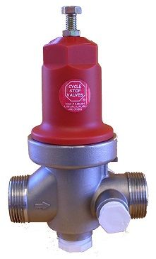
Cycle Stop Valve CSV1A
ITEM#
IV CSV1A-CONFIG
The CYCLE STOP VALVE model CSV1A is a pump control valve that automatically adjusts pump output to match variable flow requirements.
Read More
Coming Soon
As low as
USD$328.96
| Product No. | Size | Type | Pressure | Max Shut Off Head |
Max temperature |
Flow Range | Maintains constant outlet pressure |
Tank fill rate approximately |
Materials | |
|---|---|---|---|---|---|---|---|---|---|---|
| IV CSV1A Choose this option | 1'' | Threaded |
15-150 PSI 150-300 PSI available |
400 PSI |
180° F 82° C |
1-25 gpm | Yes | 1 gpm |
304 Stainless Steel Molded thermoplastic spring cage EPDM with dacron cloth insert diaphragm |
Choose this option |
The Cycle Stop Valve model CSV1A are pump controlvalve that automatically adjust pump output to match variable flow requirements.Downstream of the CSV1A pressure remainsconstant as long as demand is between the upper and lower limits of thevalve. The 1” CSV1A handle from 1-25 GPM.
As flow rates vary, the change in pressure causes the valve inside thesemodels to modulate closer to or farther away from the valve seat. Thisenables the pump to exactly match your demand and the pressure downstreamof the CSV to remain constant depending on pressure fall off.
When there is no longer any demand on the system, the pressure begins torise and the valve is pressed against the valve seat. The valve and seat aredesigned to never be able to completely seal. The non-closing seat is sizedto allow flow of approximately 1 gpm on the 1” valves. As this flow continues past the seat, water begins to fill thepressure tank downstream of the CSV. As the pressure tank slowly fills,the system pressure will slowly rise to pressure switch shut off. (Note:Pressure switch shut off pressure must always be higher than the constantpressure held by the CSV).
Regardless of tank size, when the tank fills, the pressure downstream of theCSV rises to pressure switch shut off point and the pump will be shut off.As flow is again demanded from the system, the pressure tank will emptyand the pressure switch will start the pump.
Model CSV1A are dual threaded and are available in 1” female NPT and 1 1/4” male NPT. The “1A” model is adjustable from 15-150 PSI(150-300 PSI available). There can be no more than 125 PSI maximum differential pressure acrossany of these valves. (Difference in pressure between inlet pressure andoutlet pressure). Note: In multiple pump applications, never share a CSVwith multiple pumps. Each pump must have its own valve.
Materials
- 304 stainless steel
- Molded thermoplastic spring cage
- EPDM with dacron cloth insert diaphragm
- Replaceable acetal cartridge
Pressure - Temperature
- Max temperature 180 F
- Max shut off head 400 PSI
- Adjustable pressure 15-150 PSI w/150-300 PSI available
- Max differential pressure 125 PSI
Features
- 1-25 gpm flow range
- Variable flow with reduced pressure
- Tank fill rate 1 gpm
- All internal parts corrosion resistant and included in a drop in cartridge
- 1” female NPT thread
- 1-1/4” male pipe thread
- 2) 1/2” and 1) 3/4” additional manifold ports
What are Cycle Stop Valves?
The Cycle Stop Valve is a patented pump control valve that makes a variable flow, constant pressure pump out of most standard, constant speed pumps.
Installed between the pump and your water system, the Cycle Stop Valve(CSV) automatically chokes back the output of a pump to match the usersdemand for water.
As the gallons per minute decrease, the amperage draw decreases as well because it is the weight of the water that determines the horse power or amperage needed, not the pressure.
The CSV maintains a constant pressure for the water user when demand iswithin the recommended range for the valve model being used.
It is completely mechanical and pressure actuated. No electricity required. Constant speed pumps are now capable of providing constant pressure in variable demand situations without expensive controls, huge pressure tanks, or water towers. Pumps equipped with a CSV can operate safely from as low as 1 gpm to as much as the pump can produce.
The CSV stops pump cycling, eliminates water hammer, extends pump life, andreduces energy costs compared to a system allowed to cycle off and on excessively when demand varies.
Back Pressure?
As counter intuitive as it may seem, increasing back pressure does not make pumps work harder. Onehorse power is the measure of power it takes to lift 33,000 pounds of weight (or 3,750 gallons) one ft in oneminute. Gallons and weight are the same thing to the pump. If flow from the pump is restricted with a valve,back pressure will increase. As back pressure increases, gallons or weight decreases. As the weight or gallonsof water being lifted by the pump decreases, so does power consumption, amps, or horse power. Excess backpressure is a free by-product of horsepower. Back pressure makes pumps pull less amperage, not more. Lessamperage means motors run cooler, use less electricity, and last longer.
Minimum Flow?
While Cycle Stop Valves will increase back pressure on pumps when needed, they will never let theback pressure increase to complete shut off head. The Cycle Stop Valve can never completely close. There isalways water flowing through the valve even when in its fully closed position. This flow is derived from theminimum cooling requirements of the pump and motor. Large submersible pumps can operate on much smallerflows than .5 ft per second. Flow charts for motors running at FULL LOAD AMPERAGE are not relevant formotors pulling an average 60% of full load. As back pressure increases until the pump is only pumping minimumflow, amperage decreases, derating the motor. When pulling only 50 to 60% of full load, the derated motorcan safely pump hot water up to 140 degrees according to the charts. If a derated motor can safely pump anyamount of 140 degree water, then a tiny amount of cool water (86 degrees or less) will easily prevent themotor from overheating. Minimum cooling charts for derated motors have not been made available by themotor manufactures. Years of experience has proven many times over that motors such as a 50 HP sub willdrop from 77 amps to about 40 amps when the pump is restricted to 5 gpm flow. This 5 gpm flow of 70degree water going past the motor will increase in temperature to 78 degrees. Seventy eight degrees is noteven close to 131 degree water that the charts say can safely cool a 50 HP motor when derated by 40%. Fullspeed turbines and centrifugal pumps can operate at even lower minimum flows as their motors are cooled byair. Motor and cooling fan are still spinning at full RPM, which will keep a motor that is only pulling 60% of fullload amps very cool.
Resting Pumps and Motors?
Pumps and motors are designed for continuous operation and do not need to rest. This means theywill last longer if they run continuously than if they “cycle” off and on. Motors that are coasting along at lowamperage 24 hours a day will use less electricity than the same motor pulling full load and cycling on and offevery 10 minutes or so. Most motor and pump failures occur during start up. Starting current can be sixtimes normal running amperage. Start up tests every component of the pump and motor. Windings, bearings,shafts, impellers, splines, couplings, panels, even the generator at the power company are all tested each timea pump starts. All of these problems go away once the motor is up and running. Common sense would suggestthat the fewer times it starts and stops, the longer a motor and pump will last.
Soft Start Equipment?
Some electric companies require soft starts on larger horse power systems. Cycle Stop Valves willcompletely eliminate water hammer with or without electrical soft start equipment and will also provide thesame no load start up comparable to any electrical soft start equipment. This will reduce the electric bill if ademand charge is included.
Cavitation?
Restricting the discharge from a pump with any valve will decrease the NPSH required.The NPSH available will increase as the flow rate decreases. Increasing the NPSHA and/or decreasingthe NPSHR reduces the chance of cavitation. Recirculating water from the outlet to theinlet of an impeller can occur at low flow. The 5 GPM bypass exiting the Cycle Stop Valve will keepthis recirculating from heating up the pump. Cavitation like wear can occur if the pump chosen hasa recirculating problem such as with a loose-fitting wear ring. Pumps that are made of materialswith a high tensile strength are more resistant to wear from cavitation. When equipped with anadditional pressure sustain pilot the Cycle Stop Valve can also control cavitation at high flow ratesby limiting the maximum flow from the pump.
Csv1a specifications
Csv1a specificationsWrite Your Own Review